When using resistance temperature detectors (RTDs) for temperature measurement, the additional error can be introduced by connection wires, as wires have their own resistance which depends on the ambient temperature.
RTDs have two or three-wire configuration.
RTDs are connected with copper wires as copper wires have a low resistivity.
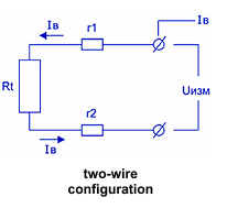
When two-wire configuration is used the temperature sensor resistance and the resistance of wires are added together, which introduces an error in the measurement result:
Rmeas= Rt+r1+r2,
where:
Rmeas – measured resistance;
Rt – sensor resistance;
r1, r2 – wire resistances.
The wire resistance depends on the ambient temperature, and so this error depends on the temperature.
That’s why, the two-wire configuration is used only at small length of wires, in cases when the wire resistance is much less than a device error.
When removing the sensor for long distances, the three-wire configuration should be applied. All three wires must be made of the same copper cable and with the same cross section and length. The maximum length of wires should not exceed 150 m.
When three-wire configuration is used, the measuring device in turn measures the resistance chain “sensor + connection wires” (Rt + r2 + r3) and the “connection wires” (r1 + r2) chain, then calculates the difference between these values and gets the exact value of the sensor resistance.
Sometimes mushroom growers try to save on the cost of wire connection and connect sensors with the help of two wires, even if the equipment supports the three-wire configuration. Consider the example of what results it can bring.
Let us suppose, the temperature sensor is located in the center of the growing room, the length of connection wire is 20 m, the wire resistivity is 0.1 ohm/m, the relative change in resistance of copper is about 0.004/°C. The wire resistance is r1 + r2 = 20 * 0.1 20 * 0.1 = 4.0 ohm at 20°C, 3.92 ohm at 15°C, 4.08 ohm at 25°C. It will lead to errors due to wires: 10.0°C at 20°C; 9.8°C at 15°C; 10.2°C at 25°C. If the part of wires is laid along the corridor where temperatures are not controlled, the error due to the two-wire configuration will be even higher.
As a rule, devices allow to enter temperature sensor corrections. In our devices it is called Offset characteristic. In the above case, when using the two-wire configuration, the offset characteristic is 10°C, but the error, caused by the temperature changes of wire connection resistance, will remain and consist 0.2°C.
We have considered the case where wires are mostly inside the growing room and the range of temperatures change is small.
In the incubation rooms the range of control temperatures is much lower – from 25 to 30°C. That’s why for your saving, it is recommended to lay two wire line inside the growing room and three-wire line out of the room to the device.
All controllers manufactured by our company for the mushroom growing make it possible to convert resistance into temperature with the error of no more than 0.1°C. It allows after finishing the installation of control system to enter corrections into the device which compensates both the sensor and connection wire errors.
To do this, after cabling is finished, one should compare readings of each channel with the measurement results of standard thermometer (please, refer to Calibration of Temperature Sensors). The given corrections should be entered into the device and make sure that the sensor deviations don’t exceed 0.1°С from the standard thermometer results.


